LD2000-PLX
AC CONTROLLER
INSTALLATION INSTRUCTIONS
The LD2000-PLX is an AC controller designed for use in bathrooms for the control of lighting and exhaust fans.
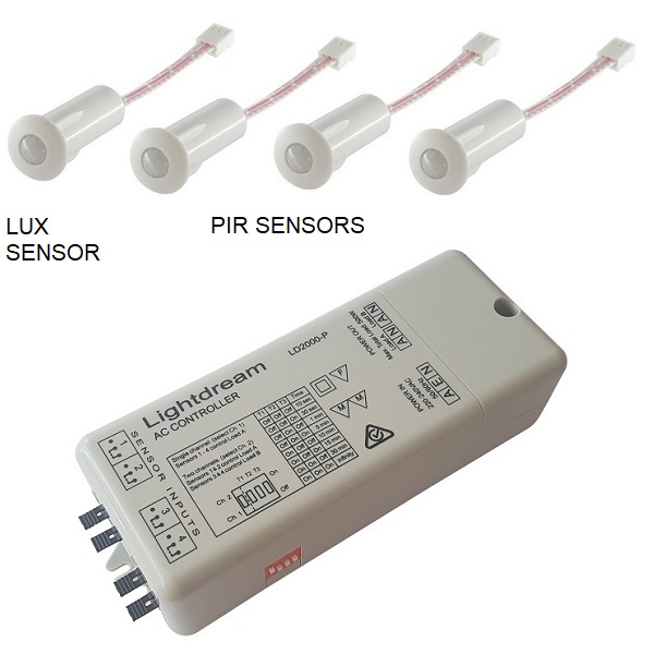
Control is via Lightdream PIR motion and lux sensors. The lux sensor is to be installed in a position where it can detect ambient light or daylight and has control over the light only.
Up to three PIR sensors and one lux sensor can be connected to each controller.
The controller is equipped with:
1 x mains power input
2 x mains power outputs
4 x sensor inputs
4 x DIP switches
CONFIGURATIONS:
1. One PIR sensor is used to control the exhaust fan and one or two PIR sensors are used to control the light.
2. One or two PIR sensors are used to control the exhaust fan and one PIR sensor is used to control the light.
In either configurations only the light is controlled by the lux sensor.
CONNECTION DIAGRAM
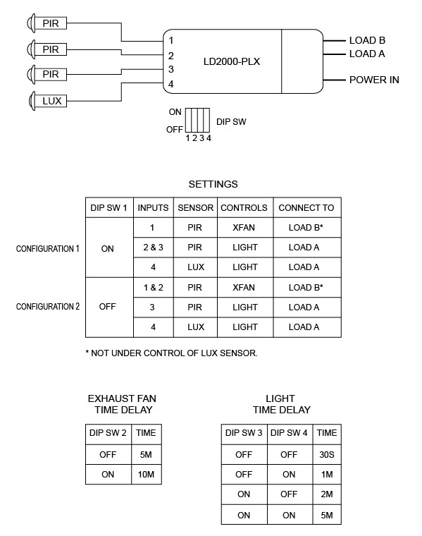
Time delay settings for the exhaust fan: 5m & 10m run time after the last movement detected.
Time delay settings for the light: 30s, 1m, 2m, & 5m run time after the last movement detected.
INSTALLATION INSTRUCTIONS
CONFIGURATION 1
PIR on input 1 controls LOAD B (exhaust fan), PIR/s on inputs 2 & 3 control LOAD A (light).
1. Connect 240V lighting load to LOAD A terminals.
2. Connect 240V exhaust fan to LOAD B terminals.
3. Connect power to ANE.
4. Remove the jumper on Input 1 and plug in the cable for the PIR sensor. (Controls exhaust fan on Load B)
5. Remove the jumper on Input 2 and plug in the cable for the first PIR sensor. (Controls light on Load A)
6. Remove the jumper on Input 3 and plug in the cable for the second PIR sensor. (Controls light on Load A)
7. Leave jumper on Input 3 if only one PIR sensor is being used for the light.
8. Remove the jumper on Input 4 and plug in the cable for the LUX sensor.
9. Push DIP SW 1 up to ON.
10. Set DIP SW 2 for time delay for exhaust fan. See table above for setting.
11. Set DIP SW 3 & 4 for time delay for lighting. See table above for setting.
12. Adjust lux sensor. Turning the dial fully anti-clockwise will allow the light to turn on in daylight. Turn the dial clockwise for the desired level.
CONFIGURATION 2
PIR/s on inputs 1 & 2 control LOAD B (exhaust fan), PIR on input 3 controls LOAD A (light).
1. Connect 240V lighting load to LOAD A terminals.
2. Connect 240V exhaust fan to LOAD B terminals.
3. Connect power to ANE.
4. Remove the jumper on Input 1 and plug in the cable for the first PIR sensor. (Controls exhaust fan on Load B)
5. Remove the jumper on Input 2 and plug in the cable for the second PIR sensor. (Controls exhaust fan on Load B)
6. Leave jumper on Input 2 if only one PIR sensor is being used for the exhaust fan.
7. Remove the jumper on Input 3 and plug in the cable for the PIR sensor. (Controls light on Load A)
8. Remove the jumper on Input 4 and plug in the cable for the LUX sensor.
9. Push DIP SW 1 down to OFF.
10. Set DIP SW 2 for time delay for exhaust fan. See table above for setting.
11. Set DIP SW 3 & 4 for time delay for lighting. See table above for setting.
12. Adjust lux sensor. Turning the dial fully anti-clockwise will allow the light to turn on in daylight. Turn the dial clockwise for the desired level.
TROUBLESHOOTING
- Is there a jumper on all unused sensor inputs?
- Are plugs tightly connected?
- Check load by connecting directly to power.
- Is lux sensor connected to Input 4.
- Adjust lux sensor, turn anti-clockwise and trigger the PIR sensor. The light should come on.
- Check the tables above for the correct configuration.
- If problems persist please phone for technical support. www.lightdream.com.au
SPECIFICATIONS
LD2000-PLX
PIR AND LUX SENSORS
Face D20mm, main body D14mm, overall length 42mm, recessed length 40mm.
Mounting hole: 14mm for plasterboard, 16mm for particleboard.
POWER
Solid-state switching of mains power with a maximum total load connected on all outputs of 500W.
Input/Output: 240VAC 50Hz
Power outputs: 2
Maximum Load (total): 500W
Switching Method: Solid-state
Sensor inputs: 4
Timer settings for exhaust fan (2): 5m, 10m
Timer settings for lighting (4): 30s, 1m, 2m, 5m
Dimensions H: 35mm, W: 56mm, L: 153mm
CERTIFICATION
EMC AS/NZS CISPR14.1:2010
Electrical Safety AS/NZS 61558; AS/NZS 3820:2009
Flammability ABS AF312C-NP 94VO