LD1403
RECESSED REED SWITCH & MAGNET
For use with Lightdream AC & DC controllers.
INSTALLATION INSTRUCTIONS
CONNECTION DIAGRAMS

INSTALLATION
1. Reed switch and magnet are to be fixed adjacent and inline with each other with the sensor-switch arrow pointing to the magnet and placed within the maximum range as shown in the diagrams below.
2. Hole diameter: 25mm.
3. If installing in a two door cabinet, hole centres are to be 100mm apart or if using the drilling template LD1410, hold it in the centre of the carcass and mark the hole centres in accordance with the chosen magnet.

4. CYLINDRICAL MAGNET: Using the drill bit guide, drill a 10mm hole in the top of each door directly adjacent to each reed switch. Ensure the depth of the hole allows the magnet to be positioned as in the cross-section diagram below.

6. DOME MAGNET: Peel off the 3M protective cover and stick to the door as in the diagram below.

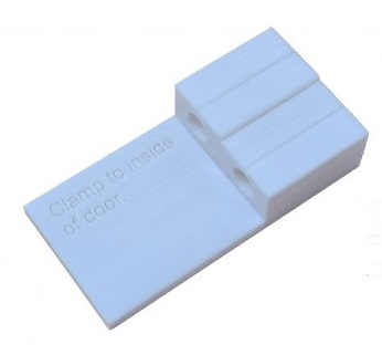
7. CUBOID MAGNET: Peel off the 3M protective cover and stick to the door as in the diagram below.

FOR USE WITH AC & DC CONTROLLERS
Available controllers are LD2000, LD2040, LD2041, LD2042 & LD2048


SPECIFICATIONS
Reed switch body: hole size 25mm, overall diameter 29mm, height 11.5mm
Cylindrical magnet: D9.5*L30mm, hole size 10mm
Dome magnet: D16*H6mm
Cuboid magnet: L28*W15*H6
Cable length: 2m
Plug: 2 pole, female, non-polarized
Compatible controllers: LD2000, LD2040, LD2041, LD2042 & LD2048 plus slave unit for LD2022 combined sensor-switch.
Warranty: 10 years